


To install the tray you will need
- 4 x M5 screws ( supplied with tray )
- M5 leader or 1st tap
- 4.2mm drill bit
- Hand held drill
- Multipurpose grease
- Small steel rule, knife or similar
After the installation ideally the gearbox should be stripped, cleaned and rebuilt, however, if this is not possible then the guide shows a little work around.
- Preparing the case.
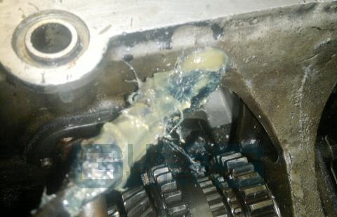
Before offering up the tray to the gearbox and if you are not intending on stripping the gearbox down after fitting, put a good quantity of grease on the areas where the holes are to be drilled. This will contain most of the alloy swarf during installation.
The key areas are
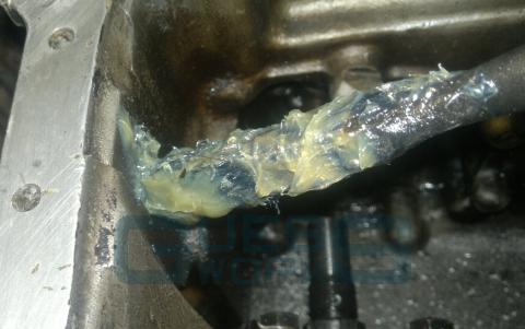
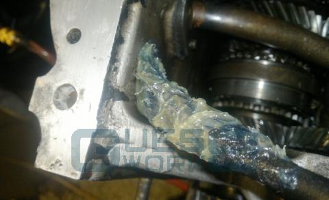
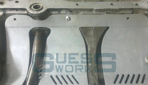
The main web
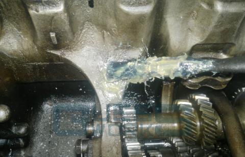
And the rear of the case either side of the mainweb and oil feed pipe
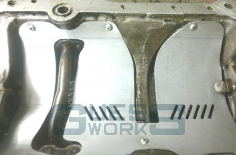
- Offering up the tray
The tray by design is a tight spring fit. It should be offered up to the case from the right, being mindful that the tray needs to go under the lump at the speedo end of the case
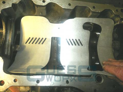
and will then locate itself into the case, once pushed down at the back over the oil feed hump
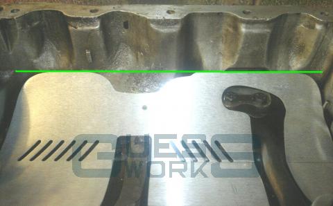
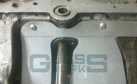
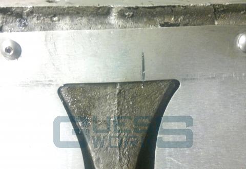
- Positioning the tray for the first hole
The first mounting hole to be drilled and tapped is the one in the main web. Doing this one first allows for a small amount of adjustment but also fixes the front of the tray in relation to an imaginary line which crosses the front of the case. This line being at the bottom of the scallops and across the top of the main web.
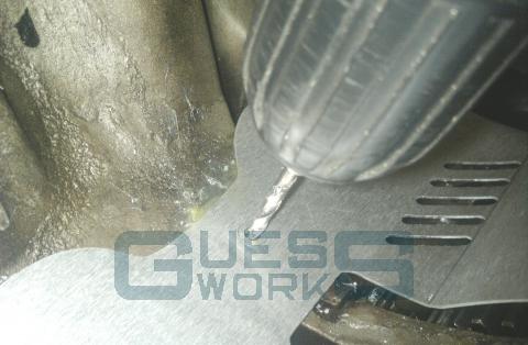
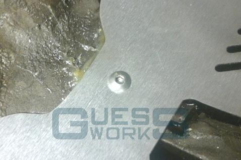
Drill and then tap the hole.
and insert the screw, just enough to nip up rather than fully tight. The tray should still twist a little on the screw.
- Positioning for the second hole
The second hole to be drilled in the centre hole of the back three. This then sets the position of the tray and the clearance of the tray over the gears and also below the crank and conrods.
Pushing down on the tray, place the rule, knife or similar on the tray and under the oil pickup pipe.
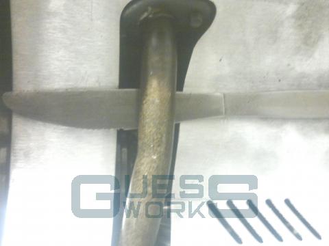
With the gearbox in 2nd gear, if you now turn the 1st motion shaft of the gearbox, you should hear the 1st/2nd synchro hub scrapping on the back of the tray. This is correct. If you do not, push the rule or knife down on the end nearest the middle of the gearbox until you do.
This sets the lowest point the tray can sit in the case.
While in this position, start to drill the hole through the middle hole and back of the case. Once the hole has started, remove the rule/knife and continue to drill.
The tray will now have a little upward pressure and the hole in the tray will slot slightly. This allows for an all important level of adjustment.
Tap the hole and install the screw, again just nipped up so a little amount of movement is available. Now press down on the tray until the 1st/2nd synchro can be heard when turning the 1st motion, and tighten the 2nd screw.
- Positioning for the third hole
To lift the tray off the 1st/2nd synchro, press down on the tray at the speedo end, just enough so the sound disappears when the gears are rotating.
This gives you the position for third hole.
Drill, tap as before allowing the upward pressure of the tray to create a small slot, and insert the screw, just nipped up.
- Positioning for the fourth and final hole
The final hole is pretty much set now.
Drill, tap as before allowing the upward pressure of the tray to create a small slot, and insert the screw, just nipped up.
- Before final adjustments
Before you do any final adjustments to the fitting the tray should be removed for cleaning, and so you can strip the gearbox if this is in plan, but also, the grease which is now filled with swarf needs to be removed
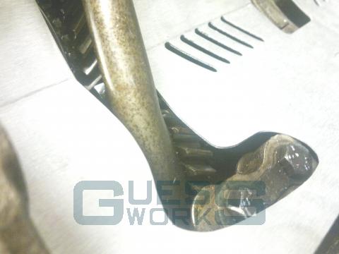
- Adjusting the tray for clearance over the gears
The aim with adjusting the tray is to get it as low into the case, but clearing the rotating gears. The amount of movement in the mounting holes will allow for this.
The picture shows that clearance over the laygear is minimal, but enough.
- Crankshaft and Conrod clearance
Once satisfied with the clearance over the gears, you should check the clearance for the crankshaft and conrods. There is really only one way to do this, which is mount the engine on the gearbox and turn the crank over.
When doing this, omit any seals, gaskets from the join, if you can get clearance without out them, then you'll have a little more clearance with.
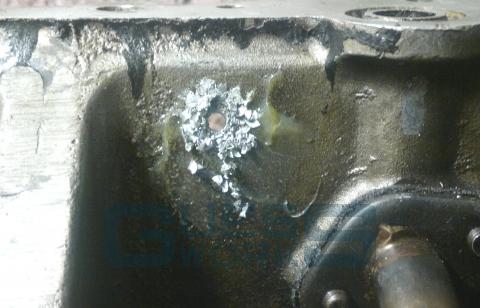
I have the advantage of a block with most of the crank case removed so I can see the clearances, but you will need to rely on your ears and feel, but the best indicator is witness marks which may be left on the tray.
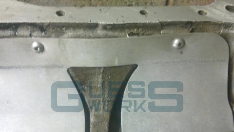
With this particular installation, the gearbox has a very high main web and with the tray going across it, caused a rub from No. 2 conrod. Other than that rub the crank and rods were clear of the tray by a substantial amount.
The solution was simple
As the mounting holes have all been set, removing the back of the tray across the web does not cause an issue, but if it can be left intact it is better too.
- Final fitting
Now sure that there is clearance on both the gears and the crankshaft and conrods, the 4 fixing screws need to be permanently fixed in position. To do this I use Loctite. Undo one screw at a time, apply the loctite and reinsert the screw, tightening to the point at which an allen key just starts to bend ( This is probably only a minimal torque ). Repeat for each screw, one at a time, therefore not allowing the tray to move from its adjusted position.