

-
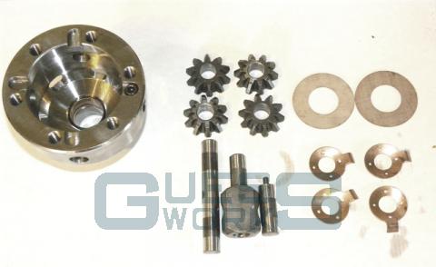
The process of building an X-pin, as supplied by Guessworks, is fairly simple and not many tools required. First make sure all your components are free from grease and dirt, a good run through the parts washer is recommended.
-
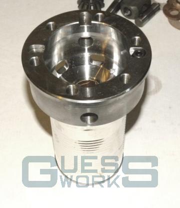
Something which I've found to be very useful aid in the building of X-pins is an old tin can.... This means the unit is held securely with enough room below to drop the output shaft in, and leaves both hands free.
-
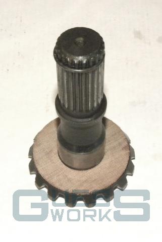
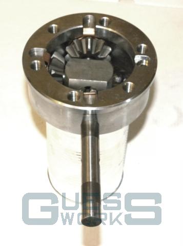
Take one of the mica/fibre thrusts and place on the output shaft. The shaft can now be placed into the unit, and should drop easily through the bush. Any tightness or slack should be investigated, this may be a product of a damaged output shaft, try another shaft if you have an issue.
-
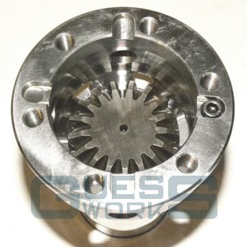
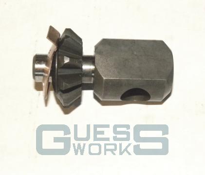
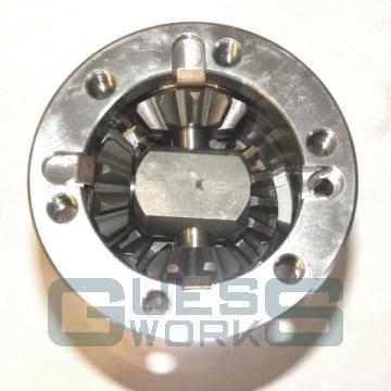
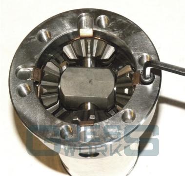
Now place one planet/pinion gear and thrust onto the block with a pin attached. Take note at this point that the pin arrangement in the x-pin is such that they are NOT at 90 degrees to each other, there is an offset. Make sure the block is rotated in the correct orientation to line up the holes. Now slide the pin, pinion and thrust into the unit, the pin should be opposite the hole with the screw, moving the gear and thrust to the end of the pin and then pushing the pin through to unit's cage.
-
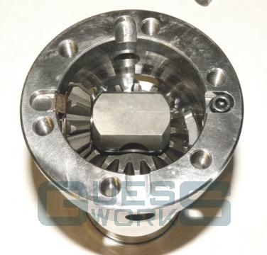
Assembly of the middle pin can begin, locate into the unit two more planets and thrusts, and then slide the long pin through the unit. Again take note of the orientation of the pin, there is a hole through the middle the large diameter side points towards the hole with the screw. If everything is lined up then this should be easy accomplished, if you feel any resistance move the obstructing item left and right with a little with light pressure on the pin and it should slide through. Avoid the temptation to use anything like a hammer, if there is insurmountable resistance, then there is something wrong in a previous step.
-
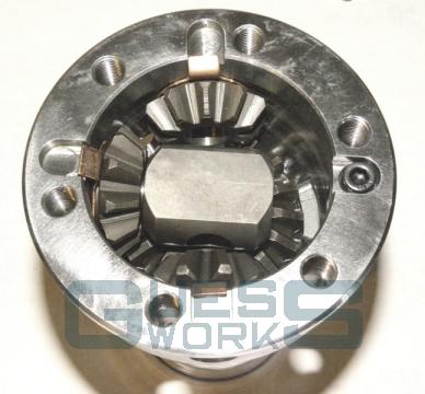
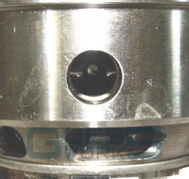
When the pin is fully home you should be able to see through the 'vacant' hole in the unit, through the middle pin and out the other side. If you can't, withdraw the middle pin enough to be able to see the hole from the top of the unit, rotate so correctly aligned and slide back in.
-
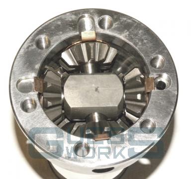
The final pinion and thrust can now be placed into the unit and the locking pin inserted. It may need a gentle tap past the machined hole for the locking screw, but under no circumstances should any heavy force be used to locate the pin into the middle shaft. It should gently lock into place. Excessive force could break the small nipple on the end of the pin rendering the pin and x-pin un-buildable until a replacement is found.
-
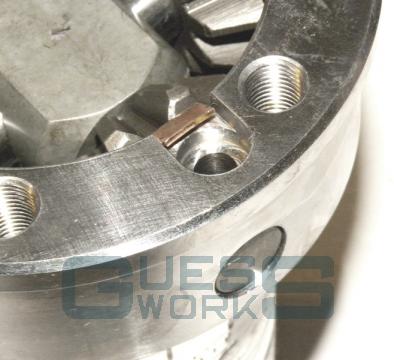
Last of all the locking screw can be inserted, but before securing in place, pick up the unit and turn the output shaft. It should turn easily with a clockwork sort of sound, over tightness ( or worse unable to turn the shaft ) should be investigated. Once satisfied, it is recommended to loctite the screw in place. You should now proceed to put the other output shaft and mica on the top of the unit and fit the crownwheel as per normal build procedures and torque settings.
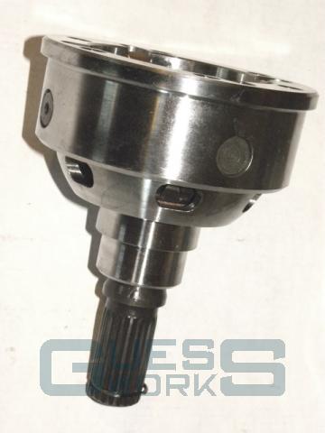
- All Guessworks supplied units have been dry built with a new output shaft and checked before being disassembled, packed and shipped so the above procedure should be easy to follow and complete.

|
|
|
|

|
|||||||||||||||
|
|||||||||||||||||||
X-Pin assembly guide |
|||||||||||||||||||
|
|||||||||||||||||||
0800 0248454or 07526 483268 |
|||||||||||||||||||